The objective of
Thermodynamic Geoengineering is to maximize the amount of the heat of global
warming converted to useful work.
It takes 100,000
square miles of solar panels to produce the equivalent of the 18 terawatts of energy consumed
globally annually. Whereas only 10,500 square miles of the ocean’s surface is
required to produce 29 terawatts with Thermodynamic Geoengineering by
converting surface ocean heat with OTEC, and the wind, solar and wave energy
that acts on and flows over and below the TG platforms.
The ratio is 80
percent OTEC and 20 percent for the other sources.
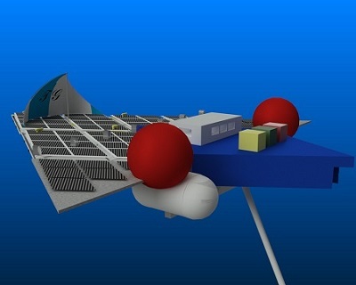
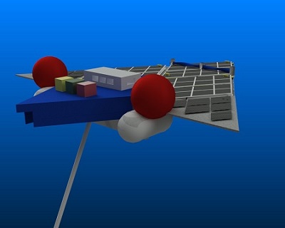
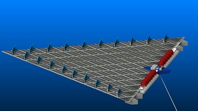
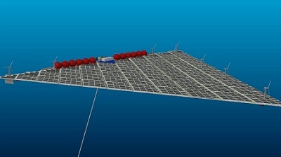
To convert surface
heat to work it is necessary to maximize the flow of warm water through the heat
exchangers shown in the " Underside of 10 MW prototype" and the "200MW plant underside"
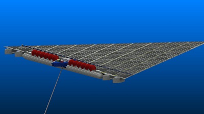
figures shown on the right. And the condensers in figures, "200 MW Isoview of bottom section" and "200 MW top of bottom section"
which are dragged behind and below the surface sections.
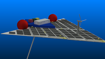
The impetus for
the platforms is provided by the three impellers shown best in the "Underside of
the 10 MW platform", which are powered by the electricity produced from the the
red, green and yellow converters that collect electricity from the windmill and
solar panels (
The trade winds,
or easterlies, are the permanent east-to-west prevailing winds that flow
in the Earth's equatorial region (between 30°N and 30°S latitudes).
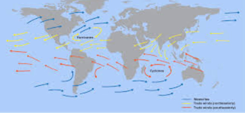
These can be harvested to produce power for the impellers when the platforms are
moving downwind and to a lesser extent by horizontal or vertical windmills when
the platforms are transiting upwind.
Thus with sails up or furled or stored.
A 10 MW prototype will be required as a proof of concept prior to scaling to
larger platforms.